Five axes — disc
The saw assembly cuts and orients the head. The records also show disc work on curved relief.

Chaosheng · Production modernization · 5 AXES — DISC + SPINDLE
Disc cutting and additional machining operations on one platform. Explore the machine in action, its features and the points that need to be defined for your production.
Explore the operations ↓The saw assembly cuts and orients the head. The records also show disc work on curved relief.
An additional machining unit broadens the range of operations. The videos show localized tool work and results with an internal opening and hole.
The “+1” identifies the additional spindle. It does not mean a sixth axis. Available movements depend on the machine configuration.
Investigate slab parts, cut orientation and disc operation sequences.
Relate geometry, tools, workholding and finish to the needs of countertops and components.
Examine additional spindle operations and the work remaining after machining.
Investigate forms compatible with the tool, material and configuration movements.
Suitability depends on the part and fabrication conditions. These examples do not establish universal capacity for materials, thicknesses or geometries.
The eight records show different aspects of the machine and presented parts. Video excerpts are not complete production cycles or performance tests.
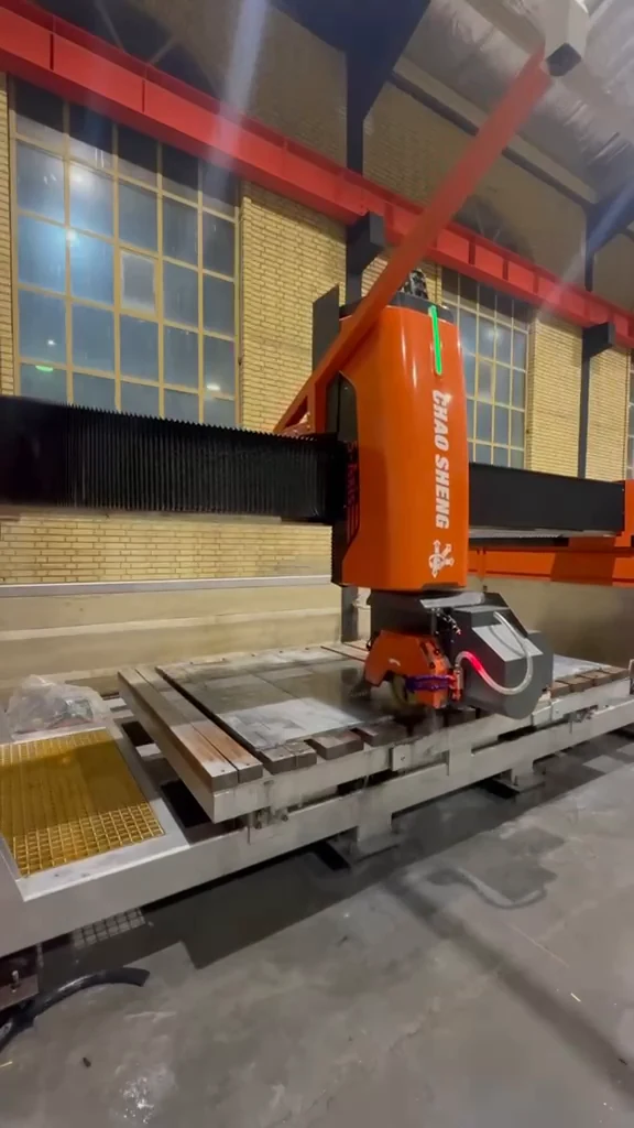
General view of the CS-Q3420-450, with the head moving and changing orientation over the table.
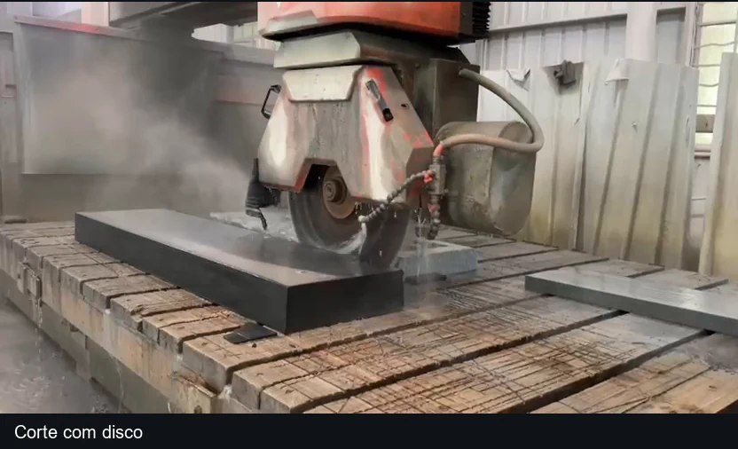
Disc cutting in a rectangular piece and a change in head orientation. The documentation describes the saw assembly as five-axis.
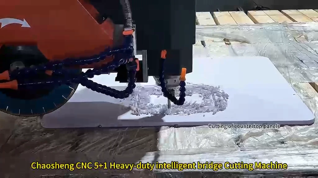
The spindle tool performs a localized operation on the slab, with visible material removal.
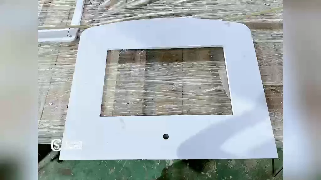
Result presented in record V019: a top with a rectangular internal opening, rounded corners and a circular hole. The same video includes a spindle operation.
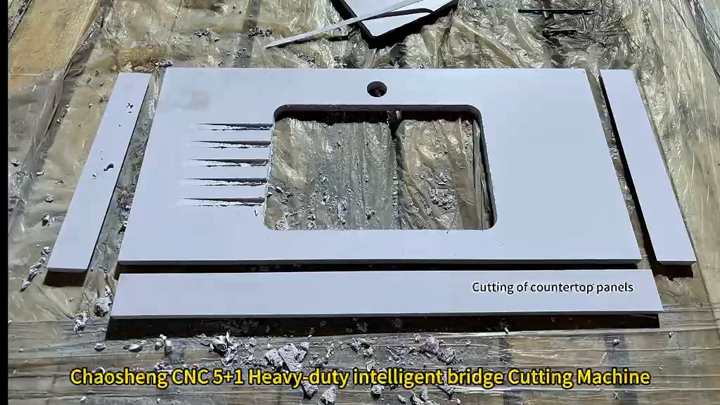
Result presented in record V016: a top with an internal opening, hole and side channels reaching the opening. The complete channel fabrication sequence is not documented.
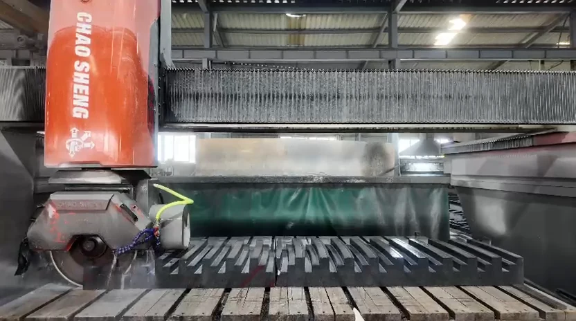
A disc working on a surface with curved ribs and grooves. In this record, the demonstrated relief is associated with the disc.
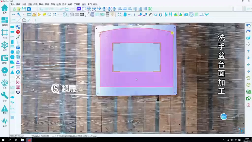
A screen with geometry overlaid on the slab image. The record shows visual positioning on the panel without documenting the entire capture and programming workflow.
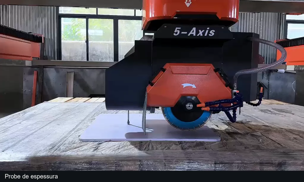
Preparation records involving disc referencing, spindle tool referencing and a probe contacting the slab.
The data sheet lists a HIKVISION camera and visual positioning. The panel shown displays geometry over an image of the slab.
Ludson describes the use of CAD files for this positioning. Accepted formats, calibration, compensation and the transition to programming need to be clarified with the manufacturer.
Slab image → panel reference → overlaid geometry
Before defining the workflow, check how the image is captured, how coordinates are related to the part and which steps depend on the operator.
Automatic referencing devices are listed in the documentation. The records show referencing stages for the disc and spindle tool.
Its function relates to tool referencing. The method, parameters and sequence must be confirmed for the configuration.
Automatic measurement is listed in the documentation. The record shows the probe contacting the slab; measurement conditions and accuracy require confirmation.
Declared range of 0–85°. Load capacity, procedures and safety conditions must accompany the configuration.
The data sheet lists two units, each with a declared safe working load of 150 kg. System capacity depends on operating conditions and must not be calculated simply by adding those values.
These features support operation. Their presence does not demonstrate automatic tool changing, wear diagnosis or fully autonomous operation.
Combining a disc and spindle brings together operations that usually need to be assessed separately. The actual benefit depends on the part, tools, fabrication sequence and selected configuration.
The values below bring together available information and outstanding questions. Processing dimensions, Z travel, height, thickness and cutting depth are different measurements.
| Model | CS-Q3420-450 |
|---|---|
| Declared architecture | Five-axis CNC bridge saw with an additional spindle |
| Declared processing dimensions | 3400 × 2000 × 450 mm. Here, 450 mm does not represent maximum stone thickness or cutting depth. The definition and order of the components require clarification. |
| Z-axis travel | Requires a specific definition from the manufacturer; not automatically inferred from the processing dimensions |
| Feeding height | 125 mm with a 450 mm disc, as listed in the data sheet; technical meaning not yet clarified |
| Stone thickness | Limits by material, tool and operation have not been established in this presentation |
| Cutting depth | Must be specified by operation and configuration |
| Disc diameter | 300–450 mm |
| Head orientation rotation | Declared angular range: −360° to +360° |
| Head tilt | Declared range: 0–90° |
| Overall dimensions | 5650 × 3300 × 4520 mm |
| Main motor | 18.5 kW in the described configuration |
| Additional spindle | 5.5 kW |
| Additional spindle speed | To be confirmed for the configuration. |
| Disc speed | To be confirmed for the configuration. |
| Declared total power | 35 kW; applicability to the selected configuration must be confirmed |
| Declared maximum travel speed | 25 m/min; not a universal cutting speed |
| Declared cutting accuracy | < 0.1 mm; test conditions not provided |
| Camera | HIKVISION; visual positioning declared |
| Table tilt | 0–85° |
| Vacuum cups | Two units; declared safe working load of 150 kg per unit |
| Referencing devices | Disc and tool |
| Probe | Automatic thickness measurement declared |
| 22 kW main motor | Declared customization option; variant parameters require confirmation |
| Protective barrier | Described as optional |
| Rubber platform | Described as optional |
Declared accuracy does not establish a guaranteed tolerance for every part, material or operation.
What products, materials, dimensions and finishes must be produced?
What will be done with the disc, spindle and subsequent stages? What tooling and workholding are needed?
Which axes operate simultaneously? What is the useful travel of each axis? How are the envelope, feeding height, admissible thickness and cutting depth defined?
Which CAD formats, software, licenses and programming features are included? How are calibration, toolpaths and simulation handled?
How does the machine relate to the company’s existing equipment, team and transfers?
What are the power, water, air, drainage, foundation, access and safety requirements? What is included in tooling, installation, training, warranty and support?
Answers must identify the specific configuration and its documents, without transferring parameters from one variant to another.
An edited video’s duration is not cycle time. A demonstration should make both the result and the work needed to achieve it understandable.
Present the product, material, dimensions, operations and target volume. Include existing machines and installation conditions.
This information helps discuss a configuration that fits the operation and identify tests needed before a commercial proposal.
Assess this configuration →Write your message and describe what you want to produce. The subject is optional.
Explore other Chaosheng applications →Concept and editorial content: Ludson Zampirolli / Z-IDEA. Data and configuration are subject to technical confirmation.